Introduction
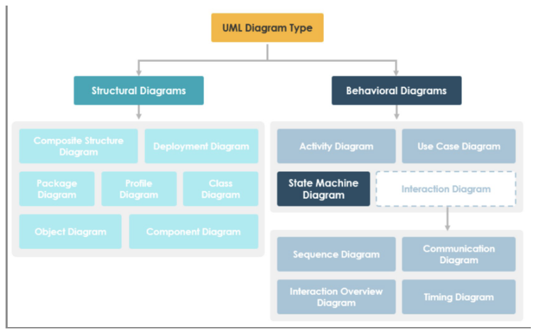
Every object takes a finite number of different stages during its life. State machine diagrams are used as follows:
- To model the possible states of a system or object.
- To show how state transitions occur as a consequence of events.
- To show what behaviour the system or object exhibits in each state.
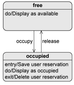
For example: high-level description of the behaviour of a lecture hall:
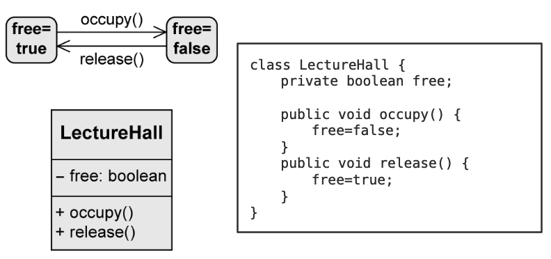
Where occupy() and release() are the transitions and “free = true”/“free = false” are the states.
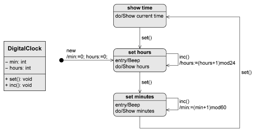
Another example would be a Digital Clock:
States
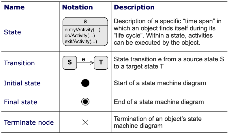
They are nodes of the state machine:
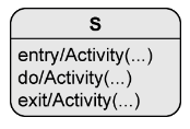
When a state is active:
- The object is in that state.
- All internal activities specified in this state can be executed, meaning an activity can consist of multiple actions.
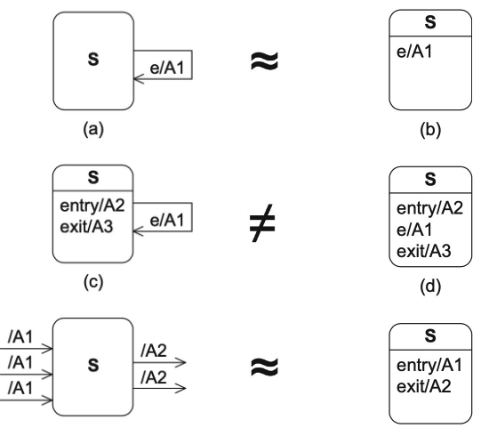
entry/Activity(…)
- Executed when the object enters the state.
exit/Activity(…)
- Executed when the object exits the state.
do/Activity(…)
- Executed while the object remains in this state.
Transitions
Syntax
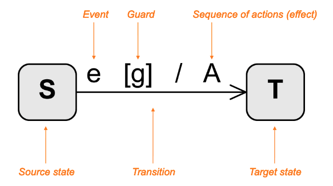
Change from one state to another:
-
Event (trigger)
- Exogenous (has an external cause or origin) stimulus.
- Can trigger a state transition.
-
Guard (condition)
- Boolean expression.
- If the event occurs, the guard is checked.
- If the guard is true:
- All activities in the current state are terminated.
- Any relevant exit activity is executed.
- The transition takes place.
- If the guard is false:
- No state transition takes place, the event is discarded.
-
Activity (effect)
- Sequence of actions executed during the state transition.
Types
- Internal:
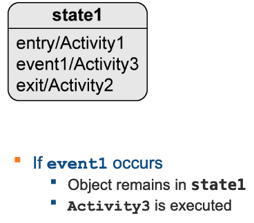
- External:
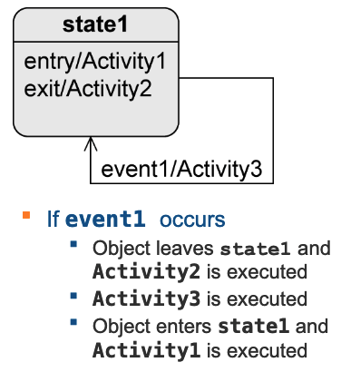
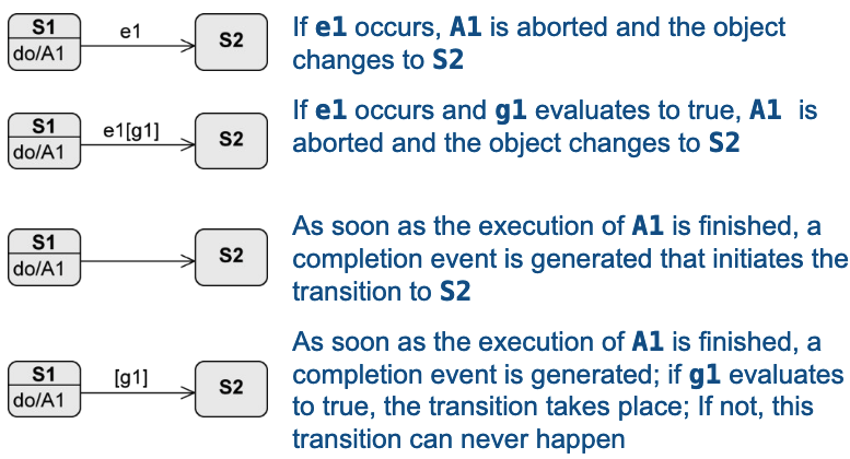
When do the following transitions take place?
Sequence of Activity Executions
Assuming is active, what is the value of after occurred?

- becomes active, is set to the value 4.
- occurs, the guard is checked and evaluates to true.
- is left, is set to 5.
- The transition takes place, is set to 10.
- is entered, is set to 11.
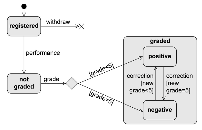
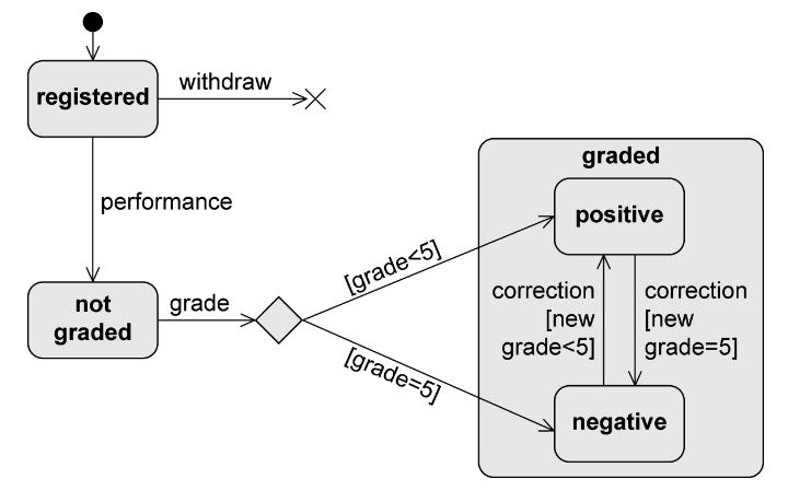
Registration status of an exam example:

Types of Events
Signal Event
Receipt of a sinal.
- e.g.:
rightmousedown,sendSMS(message).
Call Event
Operation call.
- e.g.:
occupy(user, lectureHall),register(exam).
Time Event
Time-based state transition:
- Relative: based on the time of the occurrence of the event.
- e.g.:
after(5 seconds).
- e.g.:
- Absolute
- e.g.:
when(time==16:00),when(data==20150101).
- e.g.:
Any Receive Event
Occurs when any event occurs that does not trigger another transition from the active state:
- Keyword all.
Completion Event
Generated automatically when everything to be done in the current state is complete.
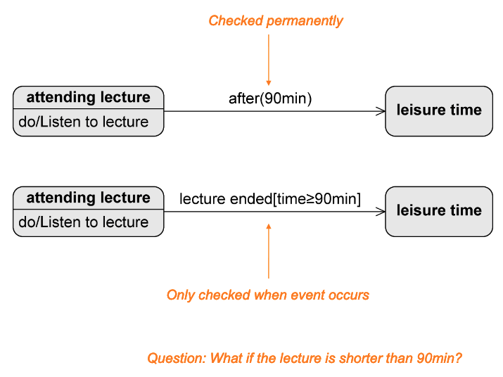
Change Event
Permanently checking whether a condition becomes true.
E.g.: when(x > y), after(90min).
Change Event vs Guard
Types of States
Initial State
It is a pseudo-state, meaning it is transient (system cannot remain in that state). It is more of a control structure than a real state.
No incoming edges.
-
If > 1 outgoing edges:
- Guards must be mutually exclusive and cover all possible cases to ensure that exactly one target state is reached.
-
If initial state becomes active, the object immediately switches to the next state.
- No events allowed on the outgoing edges (exception:
new()).
- No events allowed on the outgoing edges (exception:
Final State and Terminate Node
-
Final State
- Real state.
- Marks the end of the sequence of state.
- Object can remain in a final state forever.

-
Terminate Node
- Pseudo-state.
- Terminates the state machine.
- The modelled object ceases to exist (= is deleted).

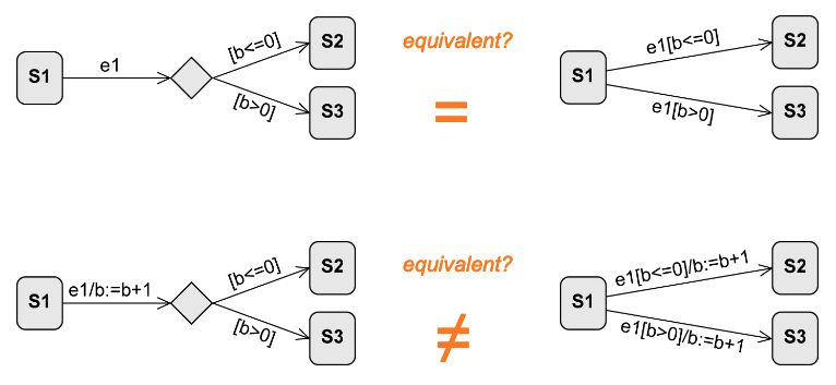
Decision Node
It is a pseudo-state and is used to model alternative transitions.
Example
Parallelisation and Synchronisation Node
-
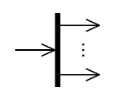
Parallelisation node
- Pseudo-state.
- Splits the control flow into multiple concurrent flows.
- 1 incoming edge.
-
1 outgoing edges.
-
Synchronisation node
- Pseudo-state.
- Merges multiple concurrent flows.
-
1 incoming edges.
- 1 outgoing edge.

Summary
