This is continuation of my notes on Use Case Diagrams from the book UML @ Classroom.
The first step is to identify actors and use cases and then place them in relationships with one another. You then describe the use cases in detail.
Identifying Actors and Use Cases
- Analysis of requirements documents.
- Analysis of the expectations of future users.
To identify the actor:
- Who uses the main use case?
- Who needs support for their daily work?
- Who is responsible for system administration?
- What are the external devices/software systems with which the system must communicate?
- Who has an interest in the results of the system?
Then you can derive the use cases:
- What are the main tasks that an actor must perform?
- Does an actor want to query or even modify information contained in the system?
- Does an actor want to inform the system about changes in other systems?
- Should an actor be informed about unexpected events within the system?
You often start with top level requirements and then continue to refine them until you have specified what the system is able to do. For example, a top level requirement for a university administration system could be that the system can be used for student administration. If we refine it, we define that new students should be able to register at the university and enroll for studies, that the students’ grades should be stored etc.
Describing Use Cases
Short concise names.
Guideline for the length of use case description is approximately 1-2 pages per use case. Structured approach:
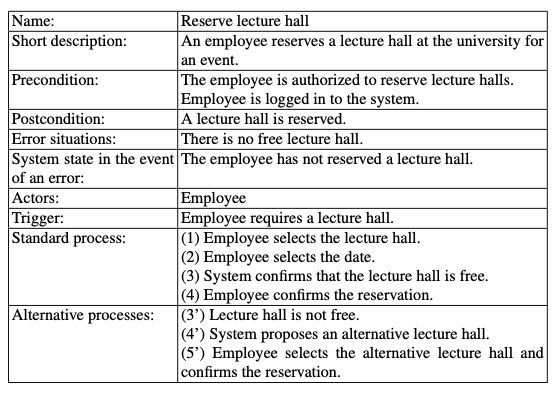
- Name
- Short description
- Precondition: prerequisite for successful execution
- Postcondition: system state after successful execution
- Error situations: errors relevant to the problem domain
- System state on the occurrence of an error
- Actors that communicate with the use case
- Trigger: events which initiate/start the use case
- Standard process: individual steps to be taken
- Alternative processes: deviations from the standard process
Example:
Pitfalls
Modeling Processes
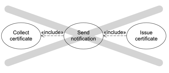
We do not model processes or workflows in use case diagrams.
The functionality that one of these use cases offers is not part of the functionality that another use case offers, hence the use cases must be used independently of one another.
Setting system boundaries incorrectly
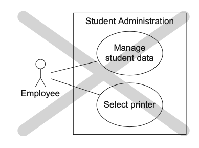
Mixing abstraction levels
Avoid representing top level use cases with technically oriented use cases in the same diagram, like in the figure below.
To avoid this you should proceed iteratively. First creating the use case diagram with use cases that are based on the business objectives (for example management of student data) and then refine the use cases down to the technical requirements (selecting a printer).
Functional decomposition
Use cases, even included or extending ones, can always be executed independently. If they can only be executed within the scope of another use case and not independently, they are not use cases and must not be depicted as such.
In the figure below, the use case Issue certificate is broken down into individual sub-functions necessary to execute it. They are modelled as use cases even though sometimes they are not meaningful independent use cases, such as Enter data.
The use case Log is not a functionality that is part of Issue certificate, it is a precondition that the user must be logged in with sufficient authorisations for being able to execute this use case.
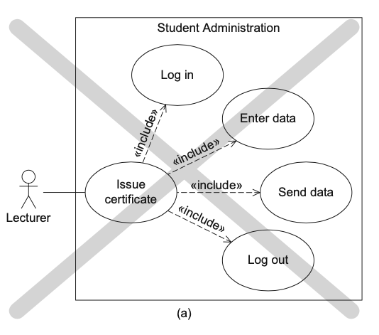
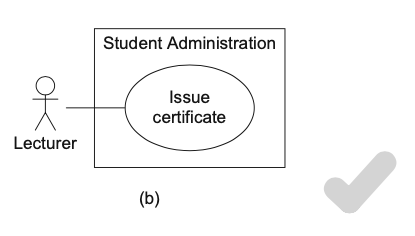
This is sufficient:
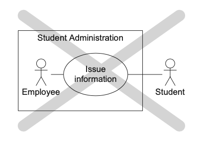
Incorrect associations
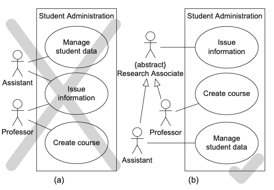
Having two actors doesn’t mean that either one of the other is involved in the execution of the use case: it means that both are necessary for its execution.
In the figure below, Assistant and Professor are involved in the execution of the use case Issue information, which is not the intention.
To resolve this, we introduce Research Associate from which the two actors inherit.
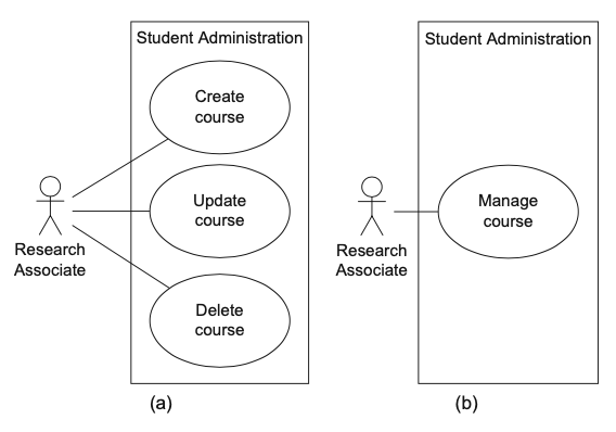
Modelling redundant use cases
As you can see in the figure below, we have modelled separate use cases for creating, updating and deleting courses. This is fine for a small diagram.
However, when modelling a real application, the diagram would quickly become unmanageable.