The LLVM Project is a collection of modular and reusable compiler and toolchain technologies. Prebuilt binaries of the LLVM toolchain can be downloaded from the LLVM Download Page. The toolchain can also be built from source by following the instructions from their documentation page. The toolchain contains the following top-level directories:
bin include lib libexec shareThe bin folder contains all the executable binaries, like the clang compiler and a set of other useful tools such as clang-rename, clang-refactor, etc.
The include folder contains a set of header files that are included during compilation. For example, the C++ header files like iostream, etc. Notice that the C header files like stdio.h are not supplied with the toolchain because they are part of the sysroot. It also contains header files that are used when using the llvm libraries to build tools.
The lib folder contains libraries like libc++, libc++abi, etc. These libraries may be used by the clang compiler during the compilation process or can be used as a reusable set of libraries.
The libexec folder contains two Python scripts that are only relevant for using the clang static analyser.
The share folder contains the documentation which can be installed as man pages and a non-essential set of scripts.
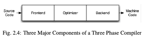
Three-phase design
Front end, optimiser and back end (as most C compilers).
- Front end: parses source code, checking it for errors and builds a language-specific Abstract Syntax Tree (AST) to represent the input code. The AST is optionally converted to a new representation for optimisation, and the optimiser and back end are run on the code.
-
Optimiser: responsible for transforming the code to improve running time, for example by eliminating redundant computations, and it is usually more of less independent of language and target.
-
Back end: aka code generator, maps the code onto the target instruction set. It is also responsible for generating good code that takes advantage of the unusual features of the supported architecture. Common parts of a compiler back end are: instruction selection, register allocation and instruction scheduling.
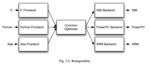
The most important win of this classical design comes when a compiler decides to support multiple source languages or target architectures. If the compiler uses a common code representation in its optimiser, then a front end can be written for any language that can compile to it, and a back end can be written for any target that can compile from it (as seen bellow).
LLVM Intermediate Representation (IR)
Is the form LLVm uses to represent code in the compiler. It is designed to host mid-level analyses and transformations that can be found in the optimisation phase.
It was designed with many specific goals in mind, including supporting lightweight runtime optimisation, cross-function/inter-procedural optimisations, whole program analyses and aggressive restructuring transformations.
The most important aspect however, is that it is itself defined as a first class language with well-defined semantics. Here is a simple example of a .ll file:
define i32 @add1(i32 %a, i32 %b) {
entry:
    %tmp1 = add i32 %a, %b
    ret i32 %tmp1
}
define i32 @add2(i32 %a, i32 %b) {
entry:
    %tmp1 = icmp eq i32 %a, 0
    br i1 %tmp1, label %done, label %recurse
recurse:
    %tmp2 = sub i32 %a, 1
    %tmp3 = add i32 %b, 1
    %tmp4 = call i32 @add2(i32 %tmp2, i32 %tmp3)
    ret i32 %tmp4
done:
ret i32 %b- Which corresponds to this C code:
unsigned add1(unsigned a, unsigned b) {
  return a + b;
}

unsigned add2(unsigned a, unsigned b) {
  if (a == 0) {
    return b;
  }

  return add2(a - 1, b + 1);
}
As you can see, the instructions (in LLVM IR) are in three address form, which means they take some number of inputs and produce a result in a different register.
It also does not use a fixed set of named registers, it uses an infinite set of temporaries named with a % character.
Beyond being implemented as a language, LLVM IR is actually defined in three isomorphic forms: the textual format above, an in-memory data structure inspected and modified by optimisations themselves, and an efficient and dense on-disk binary “bitcode” format. The LLVM Project also provides tools to convert the on-disk format from text to binary: llvm-as assembles the textual .ll file into a .bc file containing the bitcode goop and llvm-dis turns a .bc file into a .ll file.
The intermediate representation of a compiler is interesting because it can be a “perfect world” for the compiler optimiser: unlike the front end and back end of the compiler, the optimiser isn’t constrained by either a specific source language or a specific target machine. On the other hand, it has to serve both well: it has to be designed to be easy for a front end to generate and be expressive enough to allow important optimisations to be performed for real targets
LLVM’s Target Description Files: .td
Each shared component needs to be able to reason about target specific properties in a generic way. For example, a shared register allocator needs to know the register file of each target and the constraints that exist between instructions and their register operands.
LLVM’s solution to this is for each target to provide a target description in a declarative domain-specific language (a set of .td files) processed by the tblgen tool. Here is the build process for the x86 target:
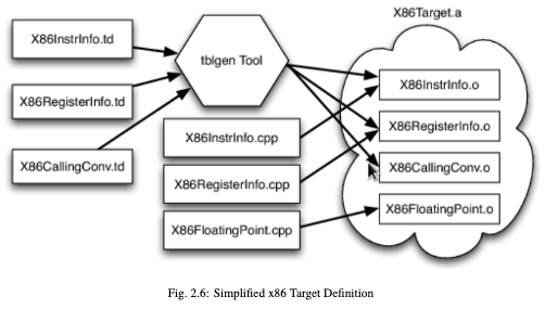
The different subsystems supported by the .td files allow target authors to build up the different pieces of their target. For example, the x86 back end defines a register class that holds all of its 32-bit registers name “GR32”, like this:
define GR32 : RegisterClass<[i32], 32,
  [EAX, ECX, EDX, ESI, EDI, EBX, EBP, ESP,
   R8D, R9D, R10D, R11D, R14D, R15D, R12D, R13D]> { ... }
The language used in the .td files are Target(Hardware) Description Language that let lvvm backend compiler engineers to define the transformations for llvm IR and the machine instructions of their CPUs.
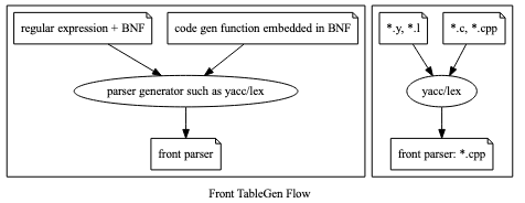
In frontend, compiler development tools provide the “ParseGenerator” for compiler development; in backend they provide the “Machine Code Generator” for development, as you can see below:

Code Generation Sequence
From tricore_llvm.pdf:
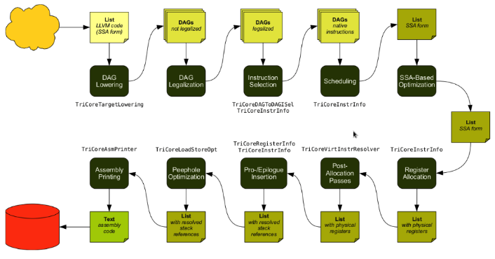
LLVM is a Static Single Assignment (SSA) based representation. LLVM provides an infinite virtual registers which can hold values of primitive type (integral, floating point, or pointer values). So, every operand can be saved in different virtual register in llvm SSA representation. Comment is “;” in llvm representation. Following is the llvm SSA instructions:
store i32 0, i32* %a  ; store i32 type of 0 to virtual register %a, %a is
                      ; pointer type which point to i32 value
store i32 %b, i32* %c ; store %b contents to %c point to, %b isi32 type virtual
                      ; register, %c is pointer type which point to i32 value.
%a1 = load i32* %a    ; load the memory value where %a point to and assign the
                      ; memory value to %a1
%a3 = add i32 %a2, 1  ; add %a2 and 1 and save to %a3
Here you can see the code generation process:
- Instruction Selection
; In this stage, transfer the llvm opcode into machine opcode, but the operand
; still is llvm virtual operand.
   store i16 0, i16* %a ; store 0 of i16 type to where virtual register %a
                        ; point to.
=> st i16 0, i32* %a ; Use Cpu0 backend instruction st instead of IR store.- Scheduling and Formation
; In this stage, reorder the instructions sequence for optimization in
; instructions cycle or in register pressure.
   st i32 %a, i16* %b, i16 5 // st %a to *(%b+5)
   st %b, i32* %c, i16 0
   %d = ld i32* %c
; Transfer above instructions order as follows. In RISC CPU of Mips, the ld
; %c uses the result of the previous instruction st %c. So it must waits 1
; cycle. Meaning the ld cannot follow st immediately.
=> st %b, i32* %c, i16 0
   st i32 %a, i16* %b, i16 5
   %d = ld i32* %c, i16 0
; If without reorder instructions, a instruction nop which do nothing must be
; filled, contribute one instruction cycle more than optimization. (Actually,
; Mips is scheduled with hardware dynamically and will insert nop between st
; and ld instructions if compiler didn't insert nop.)
   st i32 %a, i16* %b, i16 5
   st %b, i32* %c, i16 0
   nop
   %d = ld i32* %c, i16 0
; Minimum register pressure
; Suppose %c is alive after the instructions basic block (meaning %c will be
; used after the basic block), %a and %b are not alive after that.
; The following no-reorder-version need 3 registers at least
   %a = add i32 1, i32 0
   %b = add i32 2, i32 0
   st %a, i32* %c, 1
   st %b, i32* %c, 2
; The reorder version needs 2 registers only (by allocate %a and %b in the same
; register)
=> %a = add i32 1, i32 0
   st %a, i32* %c, 1
   %b = add i32 2, i32 0
st %b, i32* %c, 2-
SSA-based Machine Code Optimisation
-
Register Allocation Allocate real register for virtual register.
-
Prologue/Epilogue Code Insertion
-
Late Machine Code Optimisations Any ‘last-minute’ peephole optimisations for the final machine code can be applied during this phase.
-
Code Emission For static compilation, the end result is an assembly code file. For JIT compilation, the opcodes of the machine instructions are written into memory.
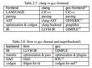
LLVM vs GCC in structure
Related to gcc.
Online resources
- LLVM Compiler Infrastructure documentation
- LLVM YouTube channel
- Tutorial LLVM backend
- LLVM Backend - Code Generator
- LLVM Official Tutorials
- Writing Your Own Toy Compiler Using Flex, Bison and LLVM
Mailing lists
Resources
Failure
Error: There is another generation process
plugin:obsidian-textgenerator-plugin:56949 TextGenerator.eval plugin:obsidian-textgenerator-plugin:56949:31
Generator.next
plugin:obsidian-textgenerator-plugin:78 eval plugin:obsidian-textgenerator-plugin:78:61
new Promise
plugin:obsidian-textgenerator-plugin:62 __async plugin:obsidian-textgenerator-plugin:62:10
plugin:obsidian-textgenerator-plugin:56935 TextGenerator.generate plugin:obsidian-textgenerator-plugin:56935:12
plugin:obsidian-textgenerator-plugin:58440 AutoSuggest.eval plugin:obsidian-textgenerator-plugin:58440:52
Generator.next
plugin:obsidian-textgenerator-plugin:78 eval plugin:obsidian-textgenerator-plugin:78:61
new Promise